

If an Arduino is running continuously it may well crash at some point. The purpose of the watchdog timer is to detect this and reset the processor. As I understand it crashes may occur because of problematic software (under unforeseen circumstances the software might get trapped in an infinite loop, for example) or the program may overwrite something important in memory, not release space used for temporary variables etc. etc. The larger the program, the greater the danger something will go wrong as memory is finite.

The watchdog timer looks at pulses which are programmed to appear on a particular Arduino pin at regular intervals as the program works through its main loop. As long as the pulses appear, the watchdog is happy. If they have not appeared for a given time the timer clamps the reset pin to zero volts for a short time which will, hopefully, clear the problem. The Arduino has a built in watchdog timer which can be activated, apparently. However, instinctively I trust an independent hardware setup more to do this job.
From my own experience, sometimes it seems to me that problems develop in the software that don’t actually cause the program to crash. Variables get very unexpected values, for example, I assume because of memory getting overwritten. Here, the watchdog timer won’t help. However, it is possible to send a command to the Arduino to reset itself by connecting a pin to the reset via a transistor which inverts the startup state of pins which is zero volts. Without the transistor, the Arduino would be in a constant reset state. The circuit below caters for both these cases.
The watchdog is more complicated than some single 555 timer circuits that I have found on the Web. These seem to be directly coupled to an Arduino pin and, as far as I can see, may not work if the pin being monitored stays low when the program crashes. Or am I missing something? (Unfortunately, that’s happened more times than I would care to remember!)
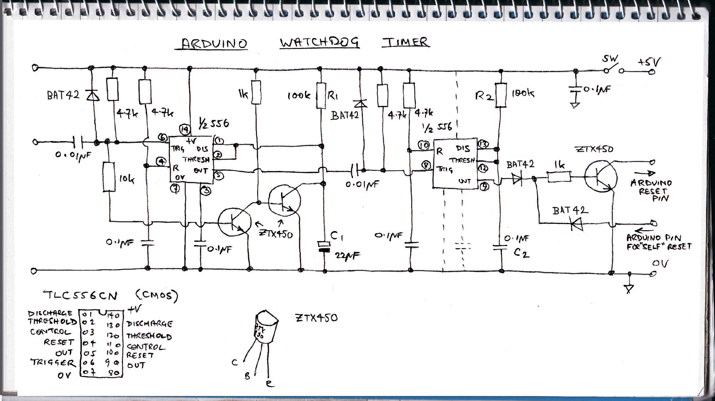
Anyway, my circuit is triggered by the transitions on pulses from the Arduino from 5 volts to zero volts (edge triggering). The input is on the left of the circuit. The 0.01 microFarad capacitor and the 4.7k resistor and the diode turn the square wave pulses into negative going spikes which can trigger the timer on the left. The output goes high and would continue to be high for a period determined by the values of R1 and C1 (for the values shown, this would be about 2 seconds) were it not for the input continuing to receive pulses from the Arduino. Each pulse acting through the two transistors effectively discharges C1 preventing the timer from timing out. (In normal operation, C1 would charge up through R1. When the voltage reached 2/3 supply voltage, the timer would time out and the output would drop to zero volts. As just described, as long as pulses are received, C1 will not reach the 2/3 supply voltage and so the output will remain high.)
However, if the pulses stop for more than about 2 seconds, the timer will time out and the output will go low. This will send a negative pulse to the second timer which will cause it to produce a 5 volt output for about 1/100 of a second. The transistor is turned on clamping the reset pin of the Arduino to zero volts for 1/100 of a second causing the computer to reset. I fitted a switch to the watchdog timer as I wasn’t sure what would happen when I downloaded a program to the Arduino and the watchdog was running. Further details of the operation of 555 (556 is the dual version) may be found in 555 Projects by EA Parr published by Babani (ISBN 0 85934 047 3). It’s an old book but very useful!
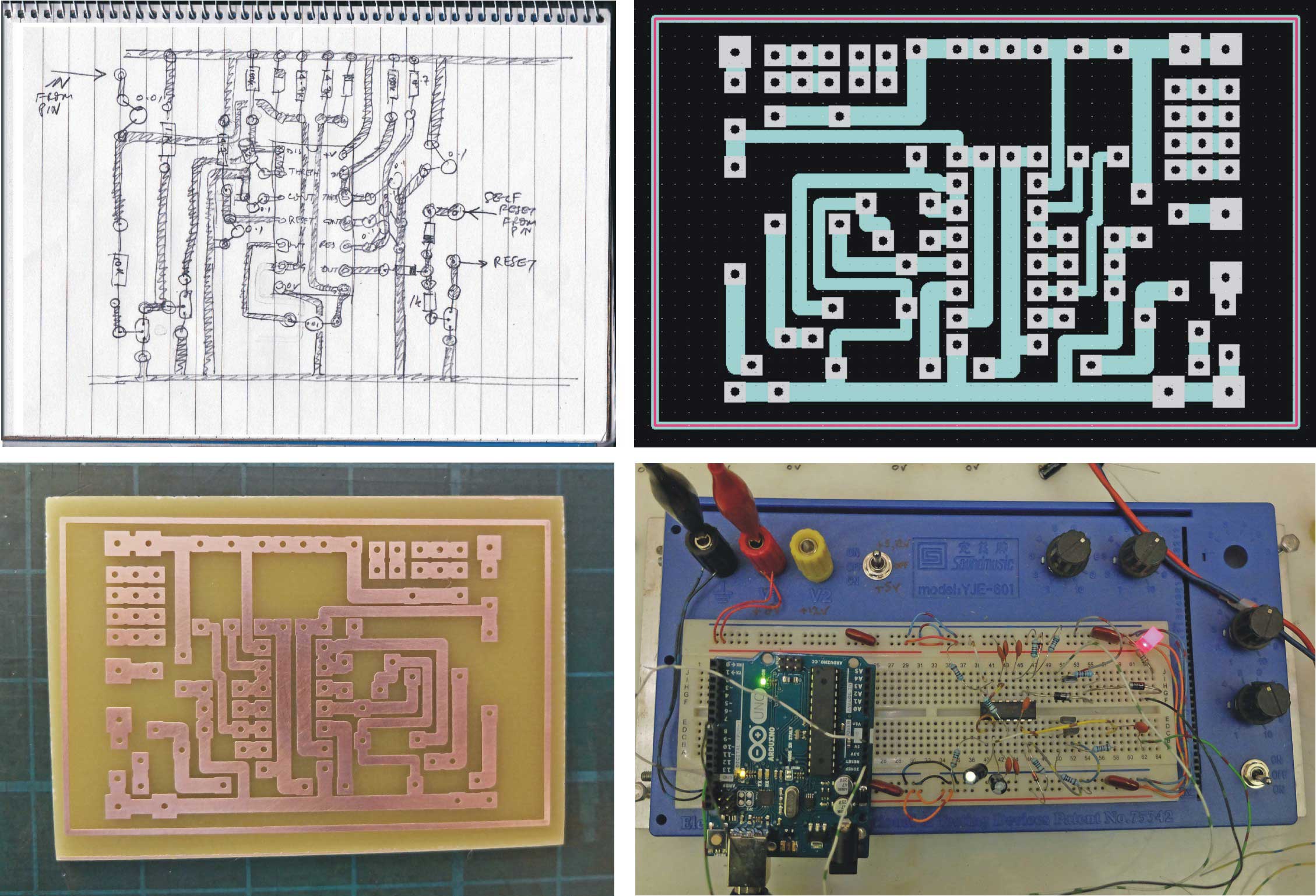
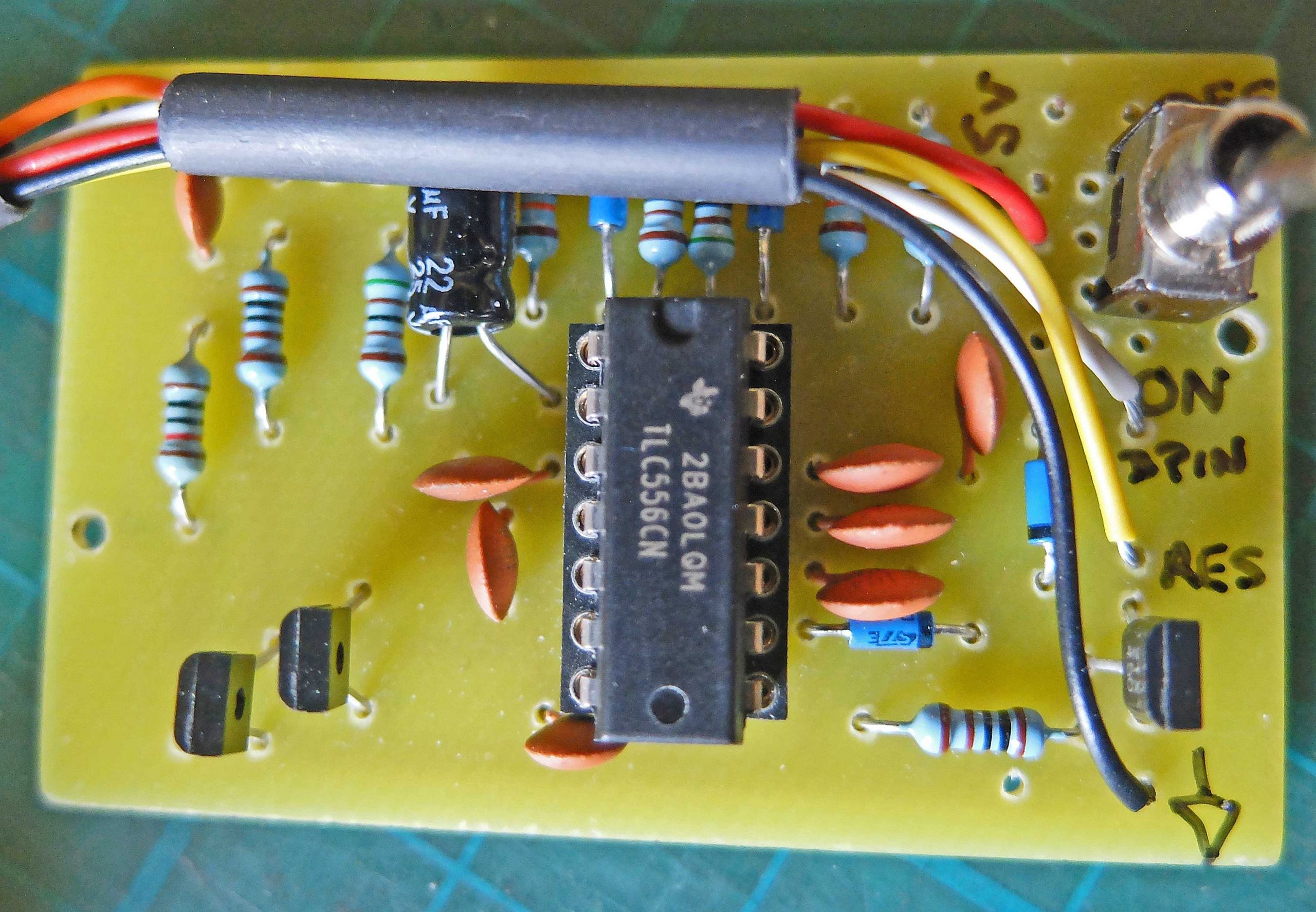
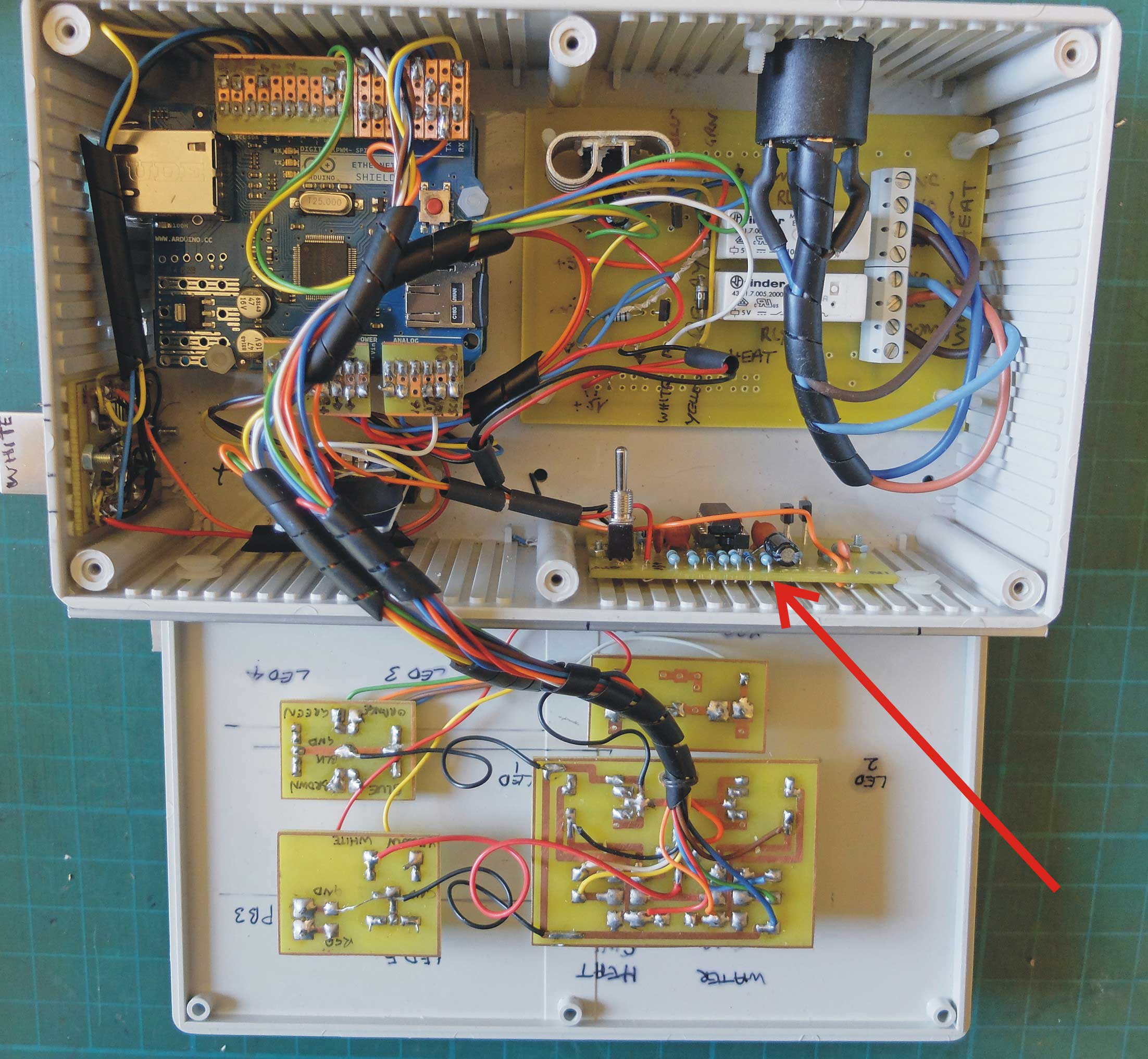
Above, clockwise from top left: 1) sketch of layout for PCB, 2) PCB design on Design Spark PCB, 3) testing the circuit on a bread board, and 4) the final PCB. Below: the completed unit.
Below are two test programs (sketches) to run on the Arduino. The first uses a for loop to generate pulses which are sent to the watchdog. When the loop finishes, the pulses stop and after a couple of seconds, the watchdog is triggered, the Arduino resets and the process is repeated.
//Watchdog
//Resets Arduino when for loop completes andLED stops flashing
void setup() {
  // initialize digital pin 13 as an output.
  pinMode(13, OUTPUT);
}

// the loop function runs over and over again forever
void loop() {

  for(int i = 1; i < 100; i++ ){
  digitalWrite(13, HIGH);   // turn the LED on (HIGH is the voltage level)
  delay(100);              // wait for a second
  digitalWrite(13, LOW);    // turn the LED off by making the voltage LOW
  delay(100);
  }
  while(true){
  }

}
In the second test program below, the Arduino resets itself by oulling its reset pin low via the ZTX450 (on the right of the circuit diagram).
//Watch dog timer test and self reset.
//

void setup() {
  // initialize digital pin 13 as an output.
  pinMode(13, OUTPUT);
  pinMode(7, OUTPUT);
}

// the loop function runs over and over again forever
void loop() {

  for(int i = 1; i < 50; i++ ){
  digitalWrite(13, HIGH);
  delay(100);
  digitalWrite(13, LOW);
  delay(100);
  }

  delay(1000);
  //if pin 7 is connected to reset via an NPN transistor, the Arduino should reset itself
  digitalWrite(7, HIGH);

  while(true){
  }

}