
I want to monitor the dampness of soil in flower beds, pots and trays etc. Accurate measurement, perhaps in terms of percentage water content by weight, is difficult. The most obvious way is to measure the electrical resistance between two or more probes. Dry soil probably is very non-conductive, wet soil very conductive. However, I suspect the result is quite dependent on the concentration of salts which break into highly conductive ions. Soil will be full of such salts. (Pure water is not very conductive!) However, most of the plants we will be using will really suffer if the soil dries out, so this is the condition I need to be able to detect.
The circuit for my meter uses my favourite 555 timer. The soil between two metal probes acts as the resistance in the capacitor/resistance timing network which governs the frequency at which the 555 pulses. The lower the resistance, the faster it pulses. The circuit has the advantage of first passing the current one way through the soil, then the other. This avoids a build up of gas at the electrodes/probes which is caused by electrolysis and will block the passage of electricity and spoil the accuracy of the sensor.
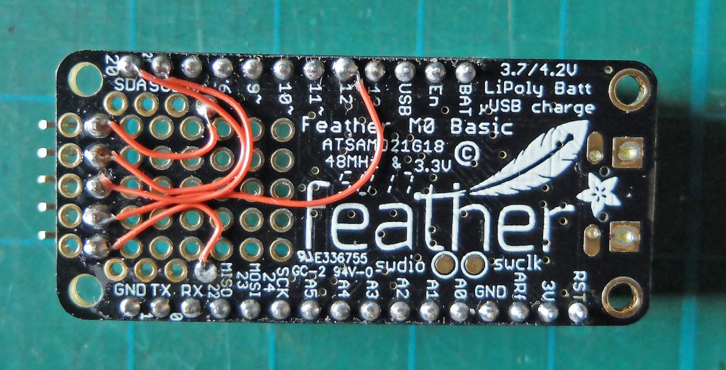
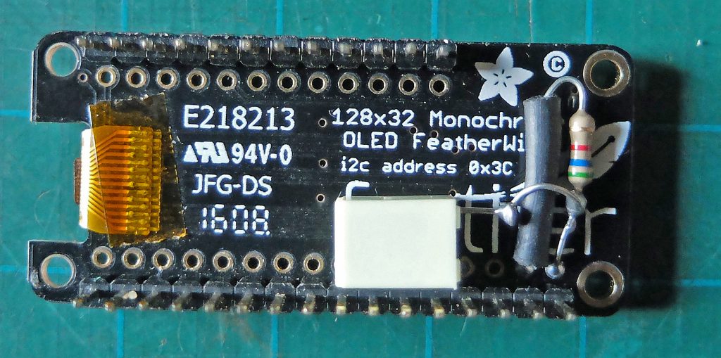
I decided to use the basic version of the Adafruit Feather M0 to measure the frequency of the pulses. This Feather just includes the processor in effect. There is a prototyping area where the various add ons such as the wifi unit normally sit. This version of the Feather is about £10 cheaper than versions with the various extras. I already had an OLED Feather Wing which, as the name suggests, features a tiny OLED display. I bought this to try it out but I hadn’t used it in a project up till now so it was available to use as a readout for my meter.
In the circuit below, I used the opto-isolator as a Schmitt trigger as I had used it in the previous circuit (to actually isolate the dampness sensor) as well as to square up the output of the 555 as at voltages lower than it was designed to operate it seems to produce a bit of a wobbly square wave. Of course, in the present circuit isolation from the soil is not an issue and I could have used a variety of other ICs (in another variation of this circuit which was connected to a central computerised monitoring station electrical isolation was needed). I could have probably done without but to be on the safe side I included the Schmitt.
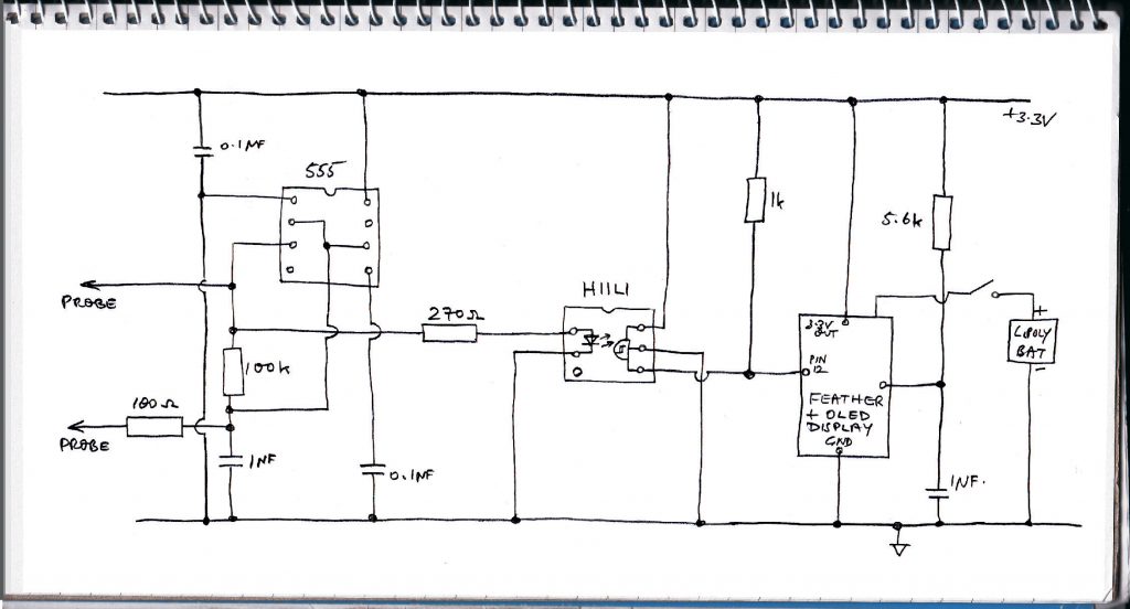
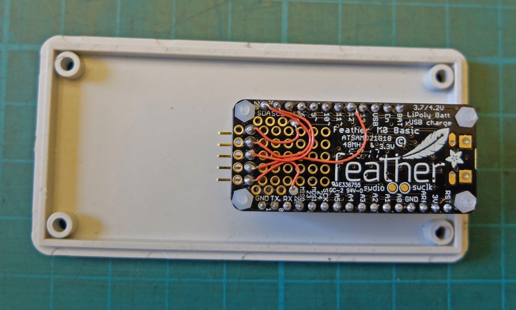
The output of the Schmitt is connected to pin 12 on the Feather. The 5.6k resistor and the 1 micro Farad capacitor are connected to the reset pin of the Feather (I notice I have forgotten to label this in the circuit above!) These are required to stop the OLED from displaying garbage on power up until the reset button is pressed. Adafruit recommend including a delay in Setup in the Feather Program to avoid this happening but that did not work for me. I wired up a 5 pin header on the prototyping area for interconnections (ground, 3.3 v, pin 12, SDA and SCL for I2C connection – I am going to include a TMP102 temperature sensor). I bodged the 5.6k and 1 micro Farad capacitor directly onto the OLED’s pcb (below).
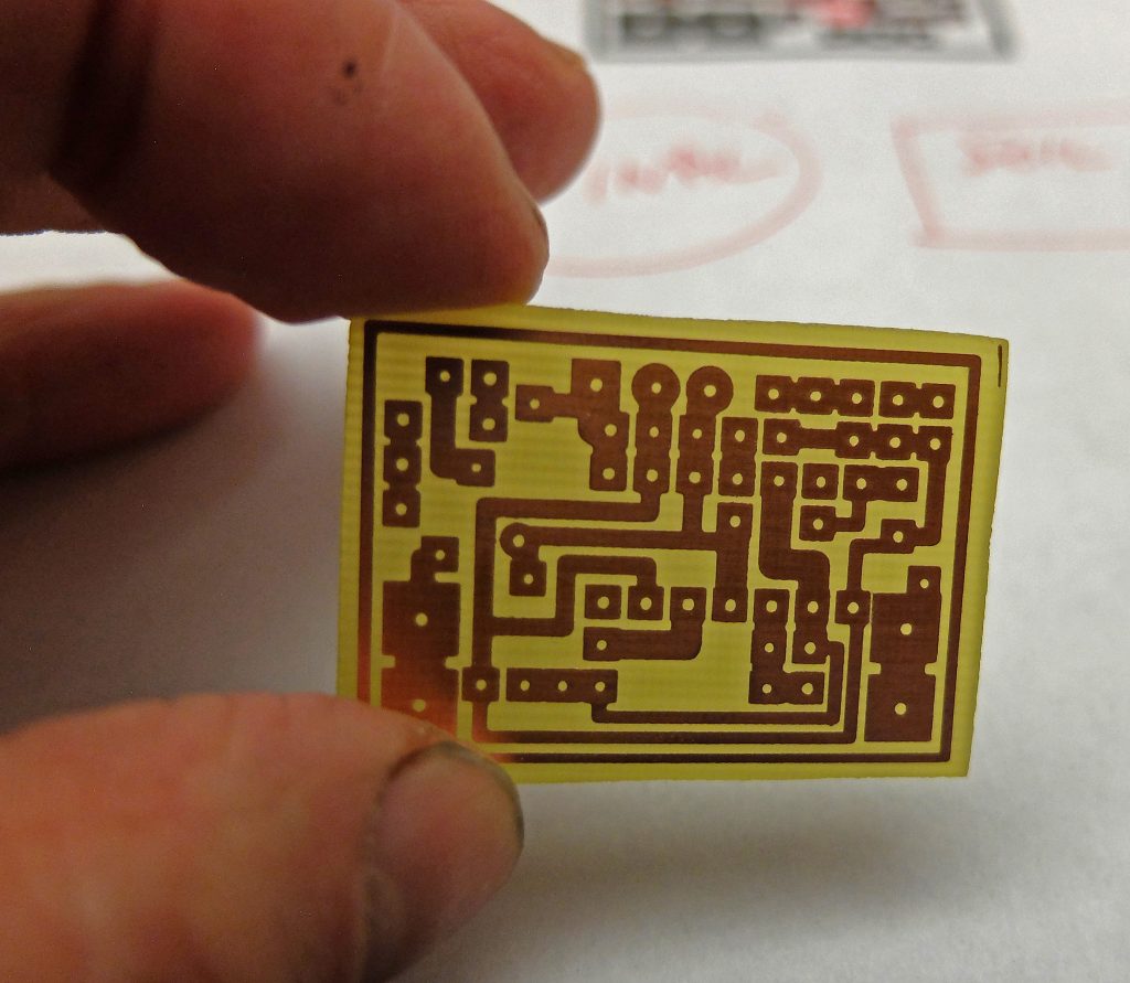
Below: I made a pcb for the circuit, making it as compact as I could. (Sorry about the grubby fingers!) This needed to be trimmed down to just beyond the inside of the outline “track” as space is tight. I had guessed that I could fit everything into a 100 x 50 x 25 box (Hammond 1591ASGY from Rapid Electronics) by laying out all the bits on the table and taking a few measurements. However, it turned out to be a bit of a squeeze!
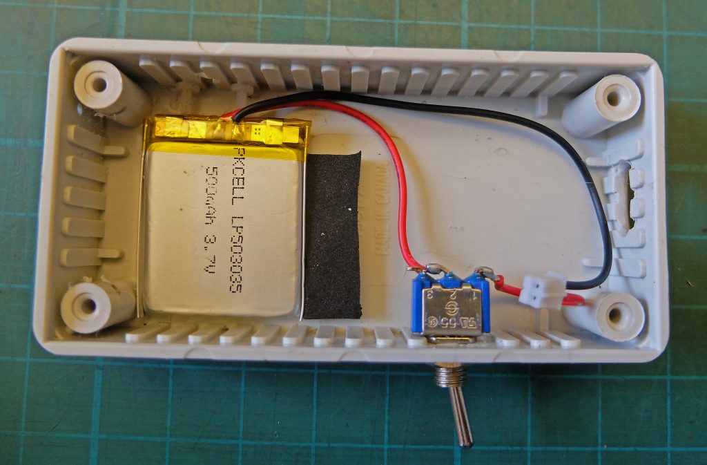
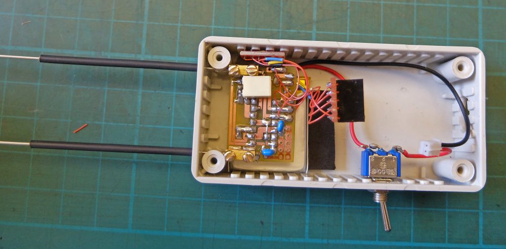
Below: This shows the battery and the power switch in position in the box. I was hoping to use a neat little momentary push button instead of the toggle switch shown here. However, I had forgotten that the battery can’t charge if it is not connected! (Charging is through the USB connector on the Feather which manages the charging of the battery.) The black rectangle is a small piece of foam glued to the box to stop the battery sliding backwards.
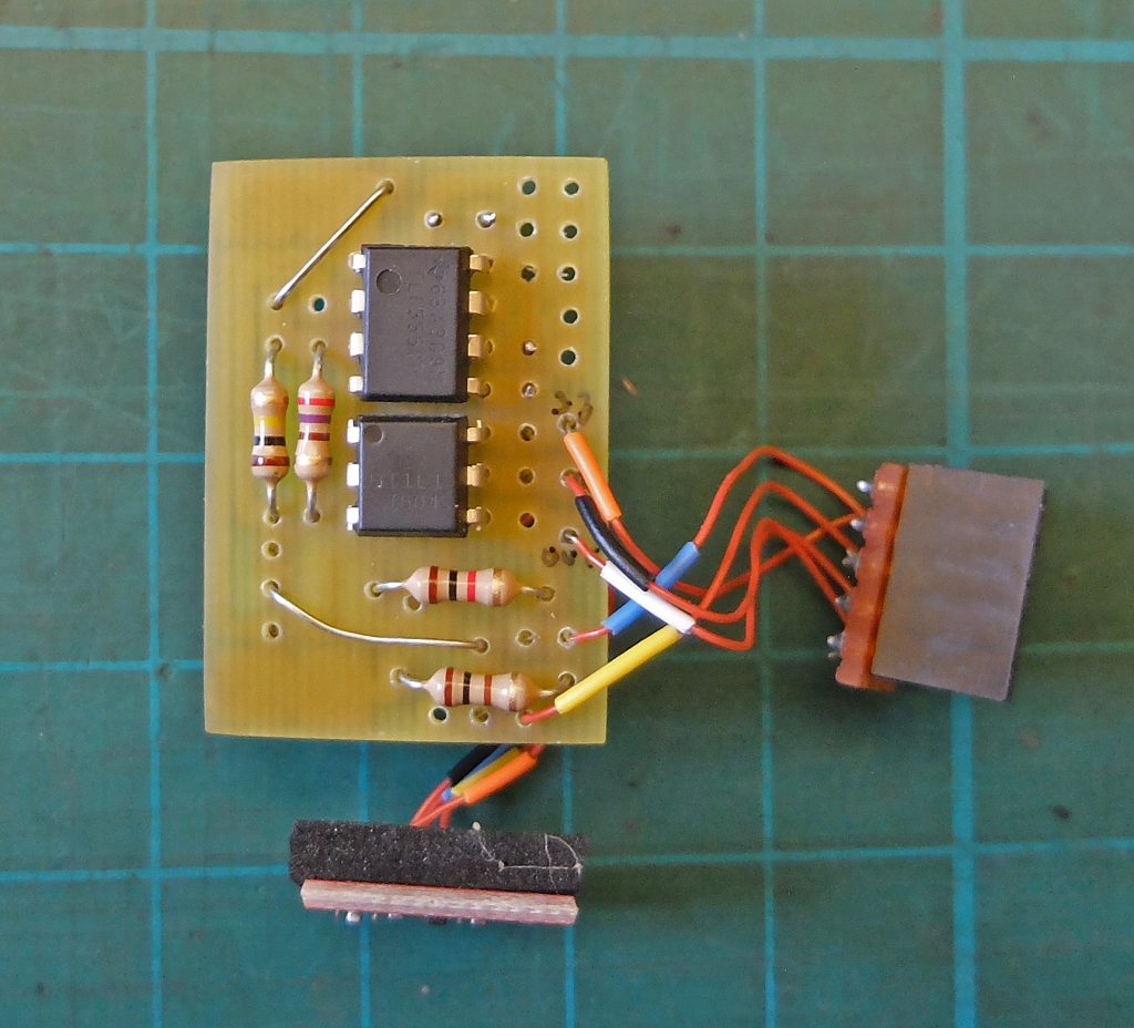
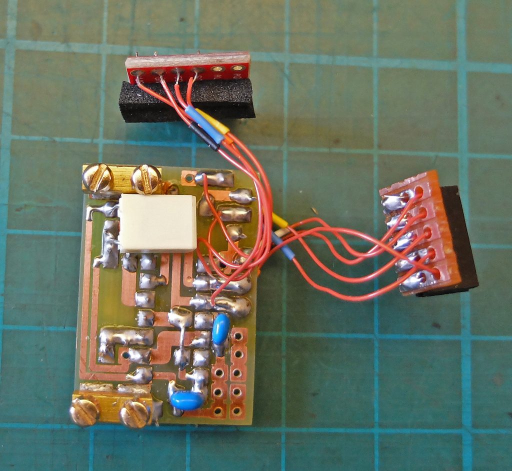
Below are the top and bottom views of the pcb. The female header which plugs into the Feather is on the right. The pcb with the small piece of foam glued to it is the TMP102 breakout board from Sparkfun. I have used this on quite a number projects now. The fine wire I have used is sold for wire wrapping and can be obtained from RS Components. I’ve put some coloured sleeves on to help with identification. These came from the wire I usually use for hookup purposes. The screw terminals were taken from 5 amp connector blocks. I filed a small flat on the underside to make soldering to the pcb easier. In order to minimise the height of the circuit, I have had to mount the capacitors on the track side of the pcb.
Below: The Feather and the OLED are screwed to the lid of the box using 2 mm nylon nuts and bolts. The four switches on the OLED are higher than the top of the display so it is necessary to drill holes to accommodate them otherwise they will be permanently held in which will not be good, especially with the reset switch!
Below: The pcb is held in place by the probes as in the sensors described previously. The two ICs just touch the battery and hold it in place. The TMP102 pcb locates on a couple of short M2 screws and the foam glued to it holds it in place.
Below: Working out where to drill holes in the lid and cut the hole for the display is a bit tricky. Adafruit publish a png file which shows the layout of the OLED pcb with dimensions. This should be imported into a graphic art program (I use a very old version of Corel Draw). Draw a rectangle the size of the box lid and superimpose it on the png picture. Move the two around until the they are in the correct relative positions (the pcb needs to be as close to the end as practicable and the display should be in the middle (it is offset on the pcb). It is not clear in the png picture, in my opinion, where the cut out for the display should be. It needs to be larger than the rectangle defined by the dotted line. The picture below gives an indication of what is required.
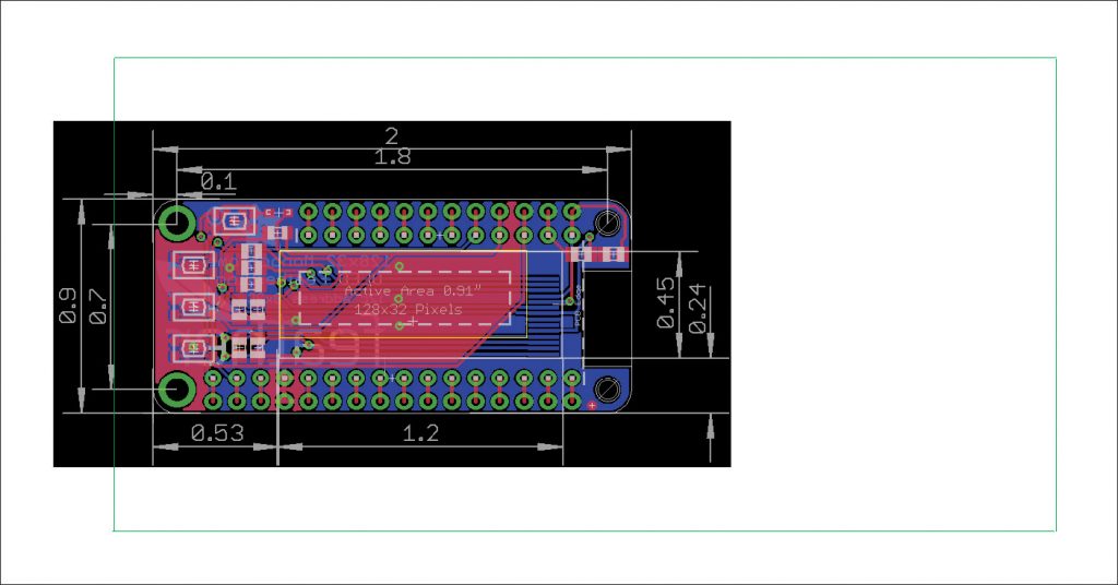
Once I was satisfied with the plan, I printed it out and cut it out along the green line which is the outline of the lid. I then applied some spray mount to the back of the plan/pattern in order to stick it to the lid so the holes and the cut out could be transferred using a sharp awl or metal point. As the edge of the lid is curved it was necessary to put some pieces of wood round the lid enabling the plan/pattern to be accurately put in place. I then used a hand drill with a 1 mm bit to drill pilot holes. This way it’t easy to feel when the drill is in the dent made by the awl and it’s harder to get the hole in the wrong place. I made a couple of large holes near the edge of the cut out and filed the hole to size.
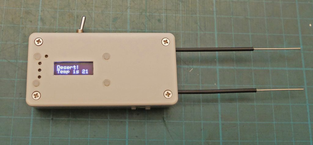
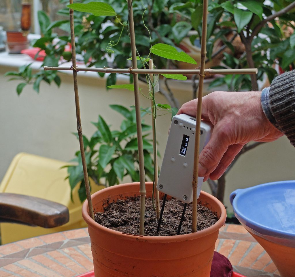
Above is the finished item. I’ve rotated the display through 180 degrees since this picture was taken making it more user friendly for right handed people. The probes are tinned coper wire clad in shrink tubing. This enables the damp content to be measured near the suface and a little further down. Ideally, I would replace these with stainless steel wires which would be stiffer. The software is listed next.
// soil dampness monitor
// dampness5
// for Feather with OLED for testing
// measures a pulse length which is related to
// the reistance between two probes which, in turn
// is related to the dampness of the soil in which
// the probes are inserted (amongst other things)
#include <SPI.h>
#include <Adafruit_SSD1306.h>
#include <Adafruit_GFX.h>
#include <Wire.h>
#define BUTTON_A 9
#define BUTTON_B 6
#define BUTTON_C 5
#define LED      13
#define TMP102_I2C_ADDRESS 0x48 // I2C address TMP102 A0 to GND
Adafruit_SSD1306 display = Adafruit_SSD1306();
int pulse_pin = 12;
unsigned long duration;
//----------------------------------------------
void setup() {
pinMode(pulse_pin, INPUT); // set pin up as input
// these pins are connected to buttons on the OLED
// not used at present
pinMode(9, INPUT_PULLUP);
pinMode(6, INPUT_PULLUP);
pinMode(5, INPUT_PULLUP);
// initialize with the I2C addr 0x3C (for the 128x32)
display.begin(SSD1306_SWITCHCAPVCC, 0x3C);
Serial.begin(9600);
// Clear the buffer.
display.clearDisplay();
display.display();
display.setRotation(2); //if you're right handed
display.setTextSize(2);
display.setTextColor(WHITE);
display.setCursor(0,0);
}
//-----------------------------------------------
// function to get temp from tmp102
int getTemp102(byte ADD_TMP102){
byte firstbyte, secondbyte; //these are the bytes we read from the TMP102 temperature registers
int val;
float convertedtemp; //We then need to multiply our two bytes by a scaling factor, mentioned in the datasheet.
Wire.beginTransmission(ADD_TMP102); // start talking to sensor
Wire.write(0x00);
Wire.endTransmission();
Wire.requestFrom(ADD_TMP102, 2);
Wire.endTransmission();
firstbyte      = (Wire.read());
//read the TMP102 datasheet - here we read one byte from
//each of the temperature registers on the TMP102
secondbyte     = (Wire.read());
//The first byte contains the most significant bits, and
//the second the less significant
val = firstbyte;
if ((firstbyte & 0x80) > 0) {
val |= 0x0F00;
}
val <<= 4;
//MSB
val |= (secondbyte >> 4);
// LSB is ORed into the second 4 bits of our byte.
convertedtemp = val*0.625; // temp x 10
//correctedtemp = convertedtemp - 0;   //should be 5 according to playground author
int temp = (int)convertedtemp;
return temp;
}
//-----------------------------------------------
void loop() {
int tempNow = getTemp102(TMP102_I2C_ADDRESS);
// measure a positive pulse in microseconds
// the large number is the maximum time to wait for a pulse
duration = pulseIn(pulse_pin, HIGH, 50000000);
duration = duration / 100;
Serial.println(duration);
display.clearDisplay();
display.setCursor(0,0);
if (duration > 680){
display.println("Atacama!");
}
else if(duration < 5){
display.println("Rainforest");
}
else if(duration < 10){
display.println("WetWetWet!");
}
else if(duration < 20){
display.println("Wet Wet!");
}
else if(duration < 30){
display.println("Wet");
}
else if(duration < 85){
display.println("Good");
}
else if(duration < 150){
display.println("Quite dry");
}
else if(duration < 200){
display.println("Dry!");
}
else if(duration < 690){
display.println("Atacama!");
}
display.print("Temp is ");
display.print(tempNow / 10);
display.display();
}
There is not a lot to the software. display.setRotation(2); in setup rotates the text on the OLED through 180 degrees which, the way I have constructed the device, suits right handed users. If you leave this line out the text is un-rotated. The three switches on pins 9, 6, 5 are available as inputs but are not used by me. Anyway, they would have to be operated with the point of a pencil or similar. My definitions of what constitutes dry, wet etc are provisional and could be revised with more experience. Originally, I had thought that I would take soil samples, dry them in the oven then gradually add weighed amount of water and so calibrate the meter but, as yet, I haven’t! One problem with this very precise method is that I believe salt content greatly affects conductivity. Anyway, great accuracy is not really required.